English-5
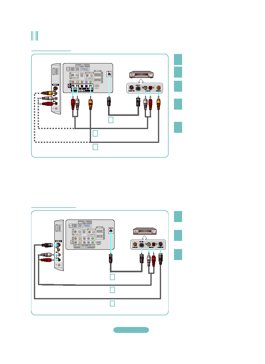
Connecting a VCR
2
3
4
If you have a “mono” (non-stereo) VCR,
use a Yconnector (not supplied) to
connect to the right and left audio input
jacks of the TV. Alternatively, connect
the cable to the “R” jack. If your VCR is
stereo, you must connect two cables.
➣
Follow the instructions in “Viewing a VCR or Camcorder Tape” to view your VCR tape.
Each VCR has a different back panel configuration.
When connecting a VCR, match the color of the connection terminal to the cable.
When connecting to AV IN 1, the color of the AV IN 1 [Y/VIDEO] jack (Green) does not match the color of the video cable
(Yellow).
➣
➣
➣
TV Rear Panel
3
RF Cable (Not supplied)
5
Audio Cable (Not supplied)
VCR Rear Panel
4
Video Cable (Not supplied)
5
Connect the cable or antenna
to the ANT IN terminal on the
back of the VCR.
Connect an RF Cable between
the ANT OUT terminal on the
VCR and the ANT IN terminal
on the TV.
Connect a Video Cable
between the VIDEO OUT jack
on the VCR and the AV IN 1
[Y/VIDEO] or AV IN 2 [VIDEO]
jack on the TV.
Unplug the cable or antenna
from the back of the TV.
Connect Audio Cables between
the AUDIO OUT jacks on the
VCR and the AV IN 1 (or AV IN 2)
[R-AUDIO-L] jacks on the TV.
Video Connection
S-Video Connection
TV Rear Panel
3
S-Video Cable (Not supplied)
RF Cable (Not supplied)
VCR Rear Panel
2
Connect Audio Cables between
the AUDIO OUT jacks on the
VCR and the AV IN 2
[R-AUDIO-L] jacks on the TV.
3
Connect an S-Video Cable
between the S-VIDEO OUT jack
on the VCR and the AV IN 2
[S-VIDEO] jack on the TV.
To begin, follow steps 1–3 in
the previous section to connect
the antenna or cable to your
VCR and your TV.
An S-Video cable may be included
with a VCR. (If not, check your local
electronics store.)
Each VCR has a different back
panel configuration.
When connecting a VCR, match
the color of the connection
terminal to the cable.
➣
➣
2
Audio Cable (Not supplied)
TV Side Panel
TV Side Panel
BN68-01393E-Eng.indd 5
2008-03-20 ¿ÀÈÄ 1:51:06